Order Information
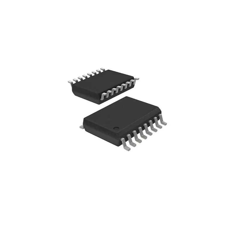
| Part No | The total number of channels | Number of reverse channels | Default output level | Package | Manner of Packing | Devices per reel |
| SSP5820ED | 2 | 0 | High | SOIC-16 | Reel | 2000 |
| SSP5821ED | 2 | 1 | High | SOIC-16 | Reel | 2000 |
| SSP5822ED | 2 | 1 | High | SOIC-16 | Reel | 2000 |
| SSP5820BD | 2 | 0 | Low | SOIC-16 | Reel | 2000 |
| SSP5821BD | 2 | 1 | Low | SOIC-16 | Reel | 2000 |
| SSP5822BD | 2 | 1 | Low | SOIC-16 | Reel | 2000 |
Pin Description
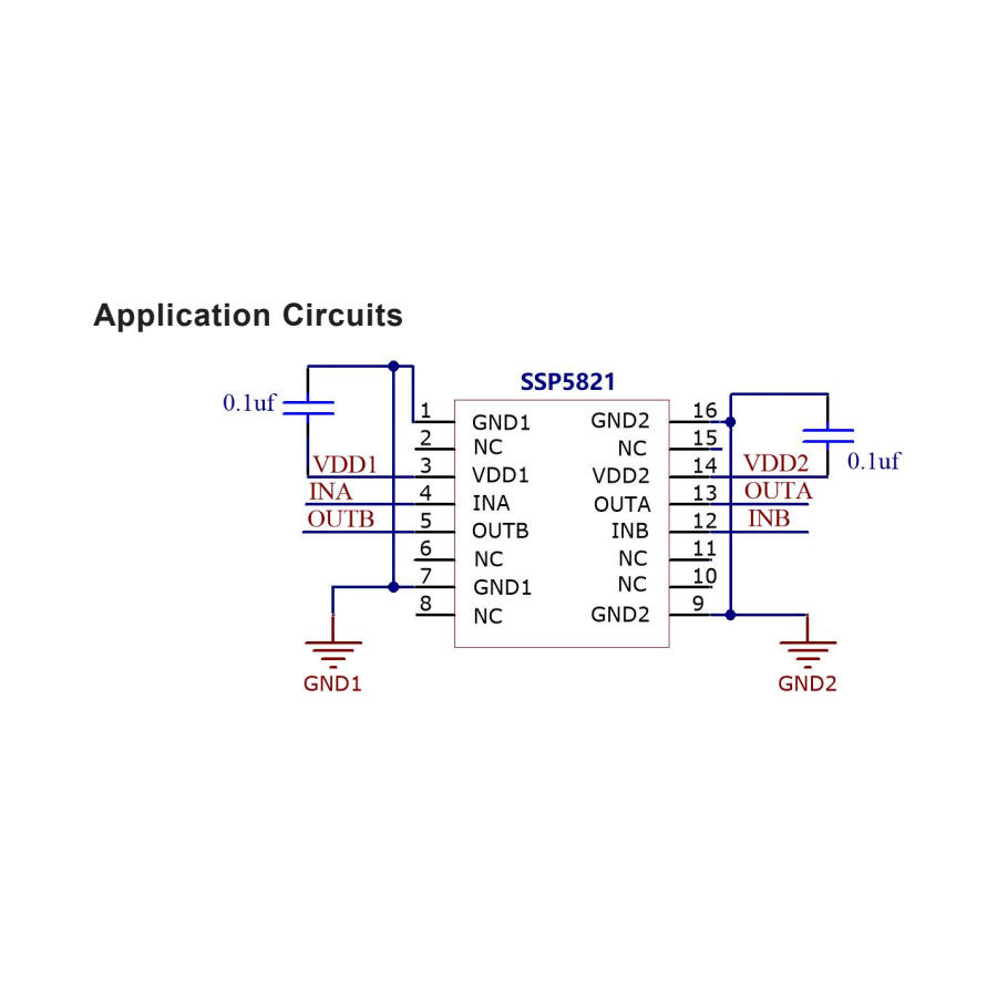
| Pin No. | Pin Name | Description |
| 1 | GND1 | Ground 1 |
| 2 | NC | – |
| 3 | VDD1 | Supply voltage 1 |
| 4 | INA | Digital signal input channel A |
| 5 | INB | Digital signal input channel B |
| 6 | NC | – |
| 7 | GND1 | Ground 1 |
| 8 | NC | – |
| 9 | GND2 | Ground 2 |
| 10 | NC | – |
| 11 | NC | – |
| 12 | OUTB | Digital signal output channel B |
| 13 | OUTA | Digital signal output channel A |
| 14 | VDD2 | Supply voltage 2 |
| 15 | NC | – |
| 16 | GND2 | Ground 2 |
Pin Description
| Pin No. | Pin Name | Description |
| 1 | GND1 | Ground 1 |
| 2 | NC | – |
| 3 | VDD1 | Supply voltage 1 |
| 4 | INA | Digital signal input channel A |
| 5 | OUTB | Digital signal output channel B |
| 6 | NC | – |
| 7 | GND1 | Ground 1 |
| 8 | NC | – |
| 9 | GND2 | Ground 2 |
| 10 | NC | – |
| 11 | NC | – |
| 12 | INB | Digital signal input channel B |
| 13 | OUTA | Digital signal output channel A |
| 14 | VDD2 | Supply voltage 2 |
| 15 | NC | – |
| 16 | GND2 | Ground 2 |
Pin Description
| Pin No. | Pin Name | Description |
| 1 | GND1 | Ground 1 |
| 2 | NC | – |
| 3 | VDD1 | Supply voltage 1 |
| 4 | OUTA | Digital signal output channel A |
| 5 | INB | Digital signal input channel B |
| 6 | NC | – |
| 7 | GND1 | Ground 1 |
| 8 | NC | – |
| 9 | GND2 | Ground 2 |
| 10 | NC | – |
| 11 | NC | – |
| 12 | OUTB | Digital signal output channel B |
| 13 | INA | Digital signal input channel A |
| 14 | VDD2 | Supply voltage 2 |
| 15 | NC | – |
| 16 | GND2 | Ground 2 |
Absolute Maximum Ratings
| Parameter | Symbol | Value | Unit |
| Supply Voltage | VDD1/VDD2 | -0.5~6 | V |
| A/B Input Voltage | V /V INA INB | -0.5~VDD1/VDD2+0.5(2) | V |
| Operating Temperature | T amb | -40~125 | ℃ |
| Junction Temperature | T J | 150 | ℃ |
| Storage Temperature | T stg | -65~150 | ℃ |
| Pin Temperature(reflow soldering) | | 260 | ℃ |
| Rated Insulation with Stand Voltage | | 5 | KVrms(3) |
Electrical Characteristics
| Parameter | Symbol | Min. | Typ. | Max. | Unit |
| Operating Temperature | T A | -40 | 25 | 125 | ℃ |
| Supply Voltage | VDD1 | 2.5 | – | 5.5 | V |
| Supply Voltage | VDD2 | 2.5 | – | 5.5 | V |
Electrical Characteristics
| Parameter | Symbol | Test Conditions | Min | Typ | Max | Unit |
| VDD Undervoltage threshold | VDD UV+ | V, V rising up DD1 DD2 | 1.9 | 2.2 | 2.37 | V |
| VDD Undervoltage threshold | VDD UV– | V, V failing down DD1 DD2 | 1.85 | 2.12 | 2.32 | V |
| VDD Undervoltage hysteresis | VDD HYS | | 50 | 70 | 95 | mV |
| Positive input threshold | V T+ | All inputs rising up | 1.4 | 1.6 | 1.9 | V |
| Reverse input threshold | V T– | All inputs failing down | 1.0 | 1.3 | 1.4 | V |
| Input Threshold Hysteresis | V HYS | | 0.38 | 0.44 | 0.50 | V |
| High Level Input Voltage | V IH | | 2.0 | – | – | V |
| Low Level Input Voltage | V IL | | – | – | 0.8 | V |
| High Level Output Voltage | V OH | loh=–4mA | VDD –0.4 | VDD –0.2 | – | V |
| Low Level Output Voltage | V OL | lol=4mA | – | 0.2 | 0.4 | V |
| Input leakage current | I L | | – | – | ±10 | µA |
| Output Impedance(1) | Z O | | – | 50 | – | Ω |
| Data Rate | | | 0 | – | 150 | Mbps |
| Minimum Pulse Width | | | – | – | 5.0 | ns |
| Propagation Delay | t, t PHL PLH | See Figure 2 | 5.0 | 9.0 | 15 | ns |
| Pulse Width Distortion |t –t | PLH PHL | PWD | See Figure 2 | – | 0.2 | 4.5 | ns |
| Part-to-Part Delay Skew(2) | t PSK(P-P) | | – | 2.0 | 4.5 | ns |
| Channel-to-Channel Delay Skew | t PSK | | – | 0.4 | 2.5 | ns |
| Rising Time | tr | CL=15pF, See Figure 2 | – | 2.2 | 4.0 | ns |
| Falling Time | tf | CL=15pF, See Figure2 | – | 2.2 | 4.0 | ns |
| Peak Eye Diagram Jitter | t JIT(PK) | | – | 350 | – | ps |
| Common Mode Transient Immunity | CMTI | VI=VDD or 0 VCM=1500V | 35 | 50 | – | kV/µs |
| Input Drop Time to Effective Output Drop Time | t SD | | – | 28 | 45 | ns |
| Startup Time(3) | t SU | | – | 15 | 45 | µs |
Truth Table
| VDD1 status | VDD2 status | Input | Output | Comment |
| P | P | H | H | Normal operation. |
| P | P | L | L | |
| P | P | X | Hi-Z | Output Disabled, the output is high impedance |
| UP | P | X | L H | Failsafe mode, the output is default. When the input power is powered on again, the signal output responds synchronously with the signal input within 1us. |
| UP | P | X | Hi-Z | Output Disabled, the output is high impedance |
Electrical Characteristics
| Parameter | Symbol | Test Conditions | Min | Typ | Max | Unit |
| Propagation Delay | t, t PHL PLH | | 5.0 | 9.0 | 15 | ns |
| Pulse Width Distortion |t –t | PLH PHL | PWD | | – | 0.2 | 4.5 | ns |
| Rising Time | tr | CL=15pF | – | 2.2 | 4.0 | ns |
| Falling Time | tf | CL=15pF | – | 2.2 | 4.0 | ns |
Electrical Characteristics
| Part No | Symbol | Parameter | Test Conditions | Min | Typ | Max | Unit |
| SSP5820Bx, Ex | V DD1 | Power Supply 1 | VI = 0(Bx), 1(Ex) | – | 0.9 | 1.5 | mA |
| V DD2 | Power Supply 2 | VI = 0(Bx), 1(Ex) | – | 1.5 | 2.3 | |
| V DD1 | Power Supply 1 | VI = 1(Bx), 0(Ex) | – | 3.4 | 5.5 | |
| V DD2 | Power Supply 2 | VI = 1(Bx), 0(Ex) | – | 1.5 | 2.4 | |
| SSP5821/2Bx, Ex | V DD1 | Power Supply 1 | VI = 0(Bx), 1(Ex) | – | 1.4 | 2.0 | mA |
| V DD2 | Power Supply 2 | VI = 0(Bx), 1(Ex) | – | 1.4 | 2.0 | |
| V DD1 | Power Supply 1 | VI = 1(Bx), 0(Ex) | – | 2.5 | 3.9 | |
| V DD2 | Power Supply 2 | VI = 1(Bx), 0(Ex) | – | 2.5 | 3.9 | |
Electrical Characteristics
| Part No | Symbol | Parameter | Test Conditions | Min | Typ | Max | Unit |
| SSP5820Bx, Ex | V DD1 | Power Supply 1 | 1Mbps Power supply current (all inputs with 500 kHz rectangular wave, all outputs with CL=15pF) | – | 2.2 | 3.2 | mA |
| V DD2 | Power Supply 2 | | – | 1.7 | 2.5 | |
| SSP5821/2Bx, Ex | V DD1 | Power Supply 1 | | – | 2.0 | 3.0 | mA |
| V DD2 | Power Supply 2 | | – | 2.0 | 3.0 | |
| SSP5820Bx, Ex | V DD1 | Power Supply 1 | 10Mbps Power supply current (all inputs with 5MHz rectangular wave, all outputs with CL=15pF) | – | 2.2 | 3.2 | mA |
| V DD2 | Power Supply 2 | | – | 2.3 | 3.4 | |
| SSP5821/2Bx, Ex | V DD1 | Power Supply 1 | | – | 2.3 | 3.4 | mA |
| V DD2 | Power Supply 2 | | – | 2.3 | 3.4 | |
| SSP5820Bx, Ex | V DD1 | Power | 100Mbps Power | – | 2.2 | 3.2 | mA |
| | Supply 1 | supply current (all inputs with 50MHz rectangular wave, all outputs with CL=15pF) | | | | |
| V DD2 | Power Supply 2 | | — | 9.0 | 12.6 | |
| SSP5821/2Bx, Ex | V DD1 | Power Supply 1 | | – | 5.9 | 8.2 | mA |
| V DD2 | Power Supply 2 | | – | 5.9 | 8.2 | |
Electrical Characteristics
| Part No | Symbol | Parameter | Test Conditions | Min | Typ | Max | Unit |
| SSP5820Bx, Ex | V DD1 | Power Supply 1 | 1Mbps Power supply current (all inputs with 500 kHz rectangular wave, all outputs with CL=15pF) | – | 2.2 | 3.2 | mA |
| V DD2 | Power Supply 2 | | – | 1.7 | 2.5 | |
| SSP5821/2Bx, Ex | V DD1 | Power Supply 1 | | – | 2.0 | 3.0 | mA |
| V DD2 | Power Supply 2 | | – | 2.0 | 3.0 | |
| SSP5820Bx, Ex | V DD1 | Power Supply 1 | 10Mbps Power supply current (all inputs with 5MHz rectangular wave, all outputs with CL=15pF) | – | 2.2 | 3.2 | mA |
| V DD2 | Power Supply 2 | | – | 2.0 | 2.9 | |
| SSP5821/2Bx, Ex | V DD1 | Power Supply 1 | | – | 2.1 | 3.1 | mA |
| V DD2 | Power Supply 2 | | – | 2.1 | 3.1 | |
| SSP5820Bx, Ex | V DD1 | Power Supply 1 | 100Mbps Power supply current (all inputs with 50MHz rectangular wave, all outputs with CL=15pF) | – | 2.2 | 3.2 | mA |
| V DD2 | Power Supply 2 | | — | 6.4 | 8.9 | |
| SSP5821/2Bx, Ex | V DD1 | Power Supply 1 | | – | 4.5 | 6.2 | mA |
| V DD2 | Power Supply 2 | | – | 4.5 | 6.2 | |
Electrical Characteristics
| Part No | Symbol | Parameter | Test Conditions | Min | Typ | Max | Unit |
| SSP5820Bx, Ex | V DD1 | Power Supply 1 | 1Mbps Power supply current (all inputs with 500 kHz rectangular wave, all outputs with CL=15pF) | – | 2.2 | 3.2 | mA |
| V DD2 | Power Supply 2 | | – | 1.7 | 2.5 | |
| SSP5821/2Bx, Ex | V DD1 | Power Supply 1 | | – | 2.0 | 3.0 | mA |
| V DD2 | Power Supply 2 | | – | 2.0 | 3.0 | |
| SSP5820Bx, Ex | V DD1 | Power Supply 1 | 10Mbps Power supply current (all inputs with 5MHz rectangular wave, all outputs with CL=15pF) | – | 2.2 | 3.2 | mA |
| V DD2 | Power Supply 2 | | – | 1.8 | 2.7 | |
| SSP5821/2Bx, Ex | V DD1 | Power Supply 1 | | – | 2.1 | 3.0 | mA |
| V DD2 | Power Supply 2 | | – | 2.1 | 3.0 | |
| SSP5820Bx, Ex | V DD1 | Power Supply 1 | 100Mbps Power supply current (all inputs with 50MHz rectangular wave, all outputs with CL=15pF) | – | 2.2 | 3.2 | mA |
| V DD2 | Power Supply 2 | | — | 5.2 | 7.2 | |
| SSP5821/2Bx, Ex | V DD1 | Power Supply 1 | | – | 3.8 | 5.3 | mA |
| V DD2 | Power Supply 2 | | – | 3.8 | 5.3 | |