


Features
| Applications
|
_画板-1@2x.png)
Blog
Features
| Applications
|
| Parameter | Test Figure | Test Conditions | ULN2001D | Unit | ||||
| MIN | TYP | MAX | ||||||
|
VI(on) |
On-state input voltage |
Figure 6 |
VCE = 2 V | IC = 200 mA | — | — | 2.4 |
V |
| IC = 250 mA | — | — | 2.7 | |||||
| IC = 300 mA | — | — | 3 | |||||
|
VCE(sat) | Collector-emitter saturation voltage |
Figure 5 | II = 250 μA, | IC = 100 mA | — | 0.9 | 1.1 |
V |
| II = 350 μA, | IC = 200 mA | — | 1 | 1.3 | ||||
| II = 500 μA, | IC = 350 mA | — | 1.2 | 1.6 | ||||
|
ICEX | Collector cutoff current | Figure 1 | VCE = 50 V | II = 0 | — | — | 50 |
μA |
| Figure 2 | VCE = 50 V, TA = +105°C | II = 0 | — | — | 100 | |||
| VF | Clamp forward voltage | Figure 8 | IF = 350 mA | — | 1.7 | 2 | V | |
| II(off) | Off-state input current | Figure 3 | VCE = 50 V, IC = 500 μA | 50 | 65 | — | μA | |
| II | Input current | Figure 4 | VI = 3.85 V | — | 0.93 | 1.35 | mA | |
| IR | Clamp reverse current | Figure 7 | VR = 50 V | TA = 25°C | — | — | 50 | μA |
| TA = 70°C | — | — | 100 | |||||
| Ci | Input capacitance | VI = 0, f = 1 MHz | — | 15 | 25 | pF | ||
Switching Characteristics
(TA = +25°C, unless otherwise specified)
| Parameter | Test Conditions | ULN2001D | Unit | |||
| MIN | TYP | MAX | ||||
| tPLH | Propagation delay time, low- to high-level output | Figure 9 | — | 0.25 | 1 | μs |
| tPHL | Propagation delay time, high- to low-level output | Figure 9 | — | 0.25 | 1 | μs |
| VOH | High-level output voltage after switching | VS = 50 V, IO = 300 mA, Figure 9 | VS–20 | — | — | mV |
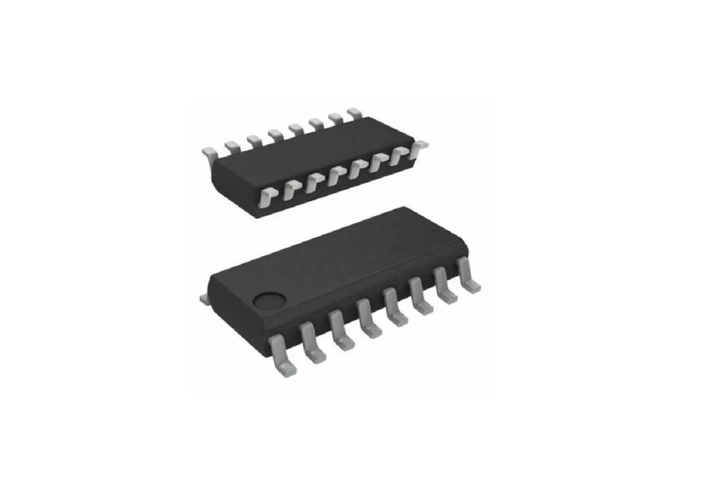
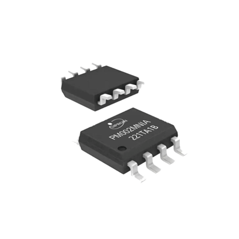
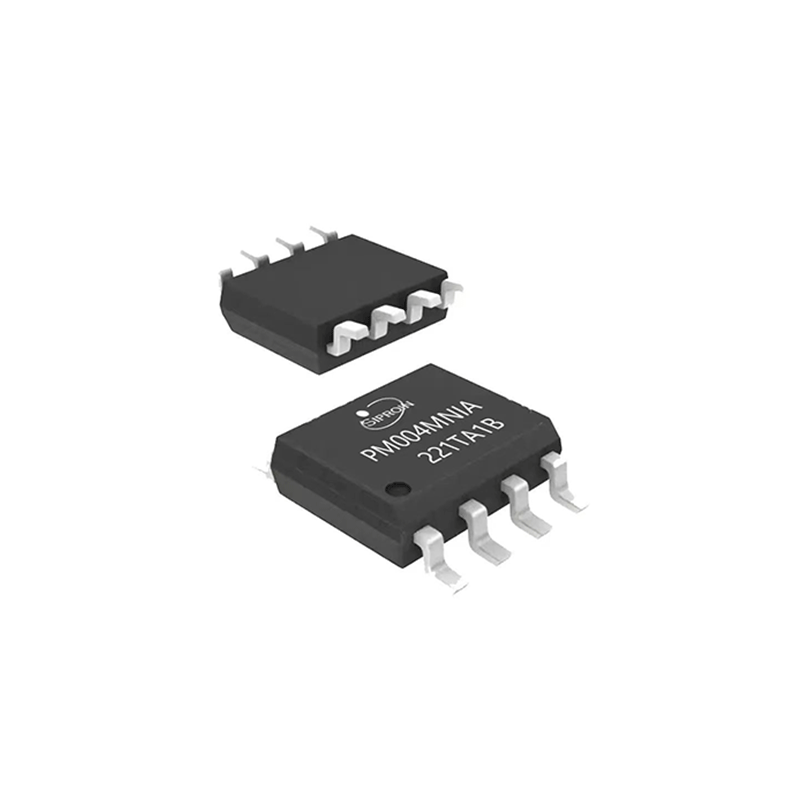
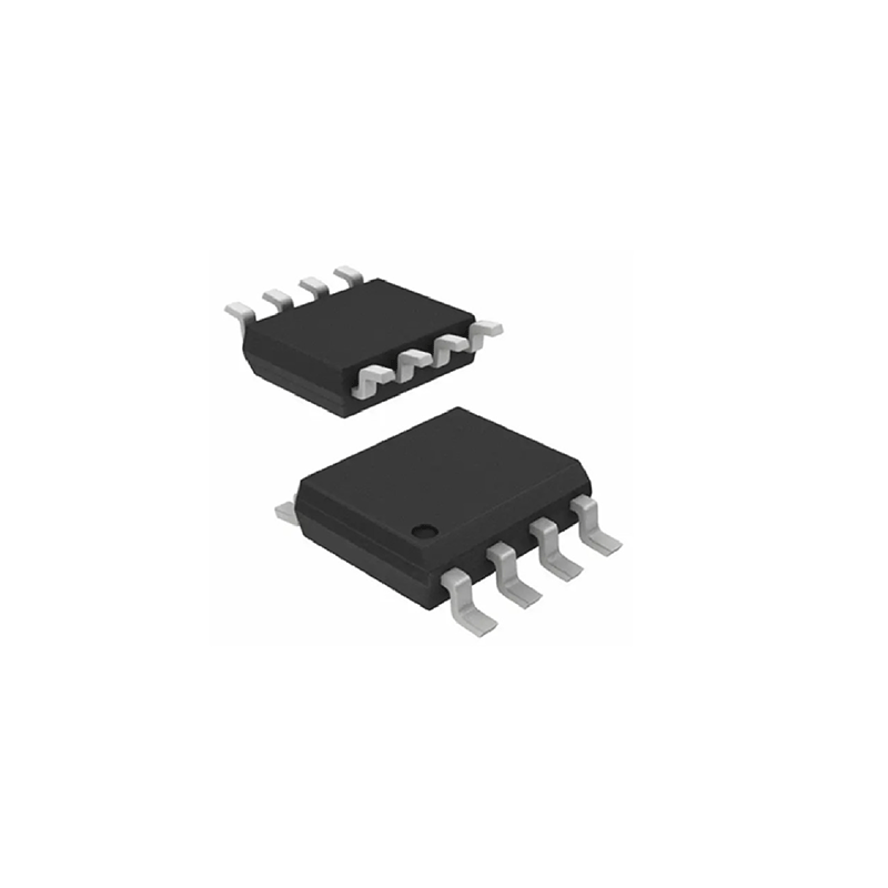
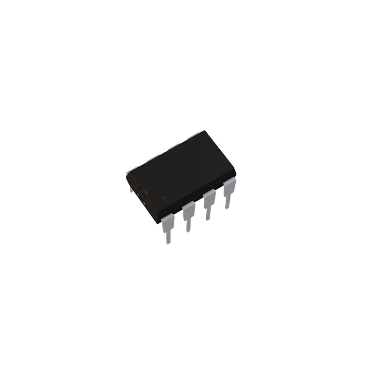
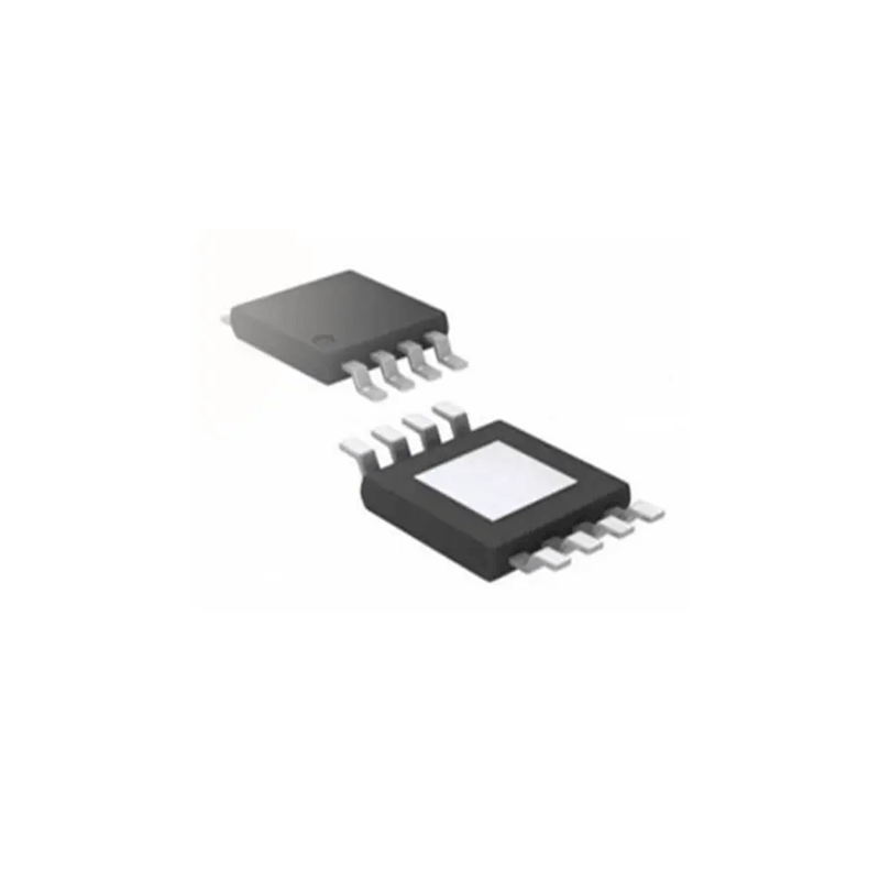
| Product model | Package | Manner of packing | Minimum packing quantity |
| ULN2001D | SOP-8 | REEL | 3500 |
| ULN2001DN | DIP-8 | TUBE | 50 |

Shanghai Siproin
Microelectronics Co.,Ltd.
Welcome your contact.

