

Features
| APPLICATIONS
|
_画板-1@2x.png)
Blog

Features
| APPLICATIONS
|
Absolute Maximum Ratings(1)
| Parameter | Min | Max | Unit | |
| Power-supply voltage | AVDD to AVSS | -0.3 | 7 | V |
| DVDD to DGND | -0.3 | 7 | V | |
| AVSS to DGND | –2.8 | 0.3 | V | |
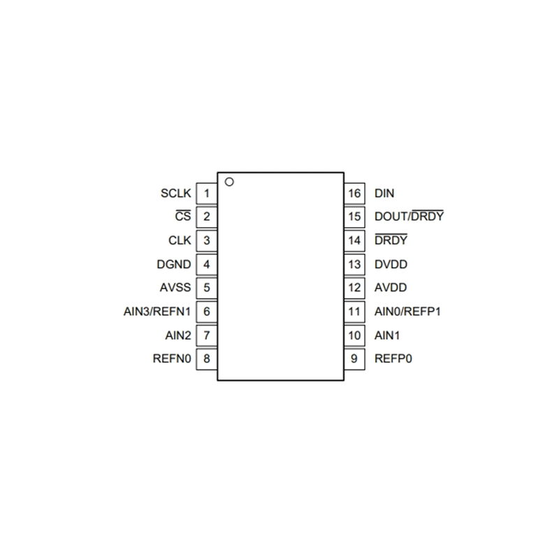
| Analog input voltage | AIN0/REFP1, AIN1, AIN2, AIN3/REFN1, REFP0, REFN0 | AVSS-0.3 | AVDD+0.3 | V |
| Digital input voltage | , SCLK, DIN, DOUT/, , CLK | DGND-0.3 | DVDD+0.3 | V |
| Input current | Continuous, any pin except power supply pins | -10 | 10 | mA |
| Temperature | Junction, TJ | -40 | 150 | ℃ |
| Storage, Tstg | -60 | 150 | ℃ |
Note (1): Stresses beyond those listed under Absolute Maximum Ratings may cause permanent damage to the device. These are stress ratings only, which do not imply functional operation of the device at these or any other conditions beyond those indicated under Recommended Operating Conditions. Exposure to absolute-maximum-rated conditions for extended periods may affect device reliability.
Electrical Characteristics
Default Test Condition: Minimum and maximum specifications apply from TA = –40°C to +125°C. Typical specifications are at TA = 25°C. AVDD=DVDD=3.3V, AVSS=0V, PGA disabled, DR=20SPS, and external Vref=2.048 V(unless otherwise noted).
| Parameter | Symbol | Test Conditions | Min | Typ | Max | Unit |
| SYSTEM PERFORMANCE | ||||||
| Resolution (no missing codes) | 16 | Bits | ||||
| Data rate | DR | Normal mode | 20, 45, 90, 175, 330, 600, 1000 | SPS | ||
| Duty-cycle mode | 5, 11.25, 22.5, 44, 82.5, 150, 250 | SPS | ||||
| Turbo mode | 40, 90, 180, 350, 660, 1200, 2000 | SPS | ||||
| Noise (input-referred) | See the Noise Performance section | |||||
| Integral nonlinearity | INL | Gain=1 to 128, VCM=0.5*AVDD, best fit | 20 | ppmFSR | ||
| Input offset voltage | VIO | PGA disabled, gain = 1 to 4, differential inputs | ±2 | µV | ||
| Gain= 1 to 128, differential inputs | ±2 | µV | ||||
| Offset drift | PGA disabled, gain = 1 to 4 | 0.1 | 0.3 | µV/°C | ||
| Gain= 1 to 128, TA= –40°C to +85°C | 0.1 | 0.3 | µV/°C | |||
| Gain = 1 to 128 | 0.3 | 0.5 | µV/°C | |||
| Gain error | PGA disabled, gain = 1 to 4 | 0.2 | % | |||
| Gain = 1 to 128, TA = 25°C | -0.5 | ±0.2 | 0.5 | % | ||
| Gain drift | PGA disabled, gain = 1 to 4 | 5 | ppm/°C | |||
| Gain = 1 to 128 | 5 | 20 | ppm/°C | |||
| Normal-mode rejection ratio | NMRR | 50 Hz ±3%, DR = 20 SPS, external CLK, 50/60 bit = 10 | 105 | dB | ||
| 60 Hz ±3%, DR = 20 SPS, external CLK, 50/60 bit = 11 | 105 | dB | ||||
| 50 Hz or 60 Hz ±3%, DR = 20 SPS, external CLK, 50/60 bit = 01 | 90 | dB | ||||
| Common-mode rejection ratio | CMRR | At dc, gain = 1 | 90 | 97 | dB | |
| f(CM) = 50 Hz, DR = 2000 SPS | 116 | dB | ||||
| f(CM) = 60 Hz, DR = 2000 SPS | 116 | dB | ||||
| Power-supply rejection ratio | PSRR | AVDD at dc, VCM= 0.5AVDD, gain= 1 | 80 | 105 | dB | |
| DVDD at dc, VCM=0.5AVDD, gain=1 | 100 | 115 | dB | |||
| INTERNAL VOLTAGE REFERENCE | ||||||
| Initial accuracy | TA = 25°C | 2.048 | V | |||
| Reference drift | -45~125°C | 5 | 30 | ppm/°C | ||
| -45~85°C | 4 | 10 | ppm/°C | |||
| 0~85°C | 3 | 7 | ppm/°C | |||
| VOLTAGE REFERENCE INPUTS | ||||||
| Reference input current | REFP0 = Vref, REFN0 = AVSS | 180 | nA | |||
| INTERNAL OSCILLATOR | ||||||
| Internal oscillator accuracy | Normal mode | -2 | ±1 | 2 | % | |
| EXCITATION CURRENT SOURCES (IDACs) | ||||||
| Current settings | 50, 100, 250, 500, 1000, 1500 | µA | ||||
| Compliance voltage | All current settings | AVDD – 0.9 | V | |||
| Accuracy | All current settings, each IDAC | -6 | ±1 | 6 | % | |
| EXCITATION CURRENT SOURCES (IDACs) | ||||||
| Current match | Between IDACs | ±0.3 | % | |||
| Temperature drift | Each IDAC | 150 | ppm/°C | |||
| Temperature drift matching | Between IDACs | 20 | ppm/°C | |||
| TEMPERATURE SENSOR | ||||||
| Conversion resolution | 14 | Bits | ||||
| Temperature resolution | 0.03215 | °C | ||||
| Accuracy | TA = 0°C to +75°C | ±0.5 | °C | |||
| TA = –40°C to +125°C | ±1 | °C | ||||
| Accuracy vs analog supply voltage | 0.1 | °C/V | ||||
| LOW-SIDE POWER SWITCH | ||||||
| On-resistance | RON | 3 | Ω | |||
| Current through switch | 30 | mA | ||||
| DIGITAL INPUTS/OUTPUTS | ||||||
| High-level input voltage | VIH | 0.7DVDD | DVDD | V | ||
| Low-level input voltage | VIL | DGND | 0.3DVDD | V | ||
| High-level output voltage | VOH | IOH = 3 mA | 0.8DVDD | V | ||
| Low-level output voltage | VOL | IOL = 3 mA | 0.2DVDD | V | ||
| Input leakage, high | IH | VIH = 5.5 V | -10 | 10 | µA | |
| Input leakage, low | IL | VIL = DGND | -10 | 10 | µA | |
| POWER SUPPLY | ||||||
| Analog supply current | IAVDD | Power-down mode | 0.05 | µA | ||
| Duty-cycle mode, PGA disabled | 135 | µA | ||||
| Duty-cycle mode, gain = 1 to 16 | 160 | µA | ||||
| Duty-cycle mode, gain = 32 | 172 | µA | ||||
| Duty-cycle mode, gain = 64, 128 | 182 | µA | ||||
| Normal mode, PGA disabled | 342 | µA | ||||
| Normal mode, gain = 1 to 16 | 448 | µA | ||||
| Normal mode, gain = 32 | 499 | µA | ||||
| Normal mode, gain = 64, 128 | 550 | µA | ||||
| Turbo mode, PGA disabled | 402 | µA | ||||
| Turbo mode, gain = 1 to 16 | 613 | µA | ||||
| Turbo mode, gain = 32 | 715 | µA | ||||
| Turbo mode, gain = 64, 128 | 817 | µA | ||||
| Digital supply current | IDVDD | Power-down mode | 1.3 | µA | ||
| Duty-cycle mode | 44 | µA | ||||
| Normal mode | 43 | µA | ||||
| Turbo mode | 73 | µA | ||||
| POWER SUPPLY | ||||||
| Power dissipation | PD | Duty-cycle mode, PGA disabled | 0.5907 | mW | ||
| Normal mode, gain = 1 to 16 | 1.6203 | mW | ||||
| Turbo mode, gain = 1 to 16 | 2.2638 | mW | ||||

Shanghai Siproin
Microelectronics Co.,Ltd.
Welcome your contact.

