

Features
| Applications
|
Blog
Features
| Applications
|
Absolute Maximum Ratings(1)
At 25°C free-air temperature (unless otherwise noted)
| Symbol | Parameter | Min | Max | Unit |
| VCC | Collector to emitter voltage | 50 | V | |
| VR | Clamp diode reverse voltage(2) | 50 | V | |
| VI | Input voltage(2) | 30 | V | |
| ICP | Peak collector current | 500 | mA | |
| IOK | Output clamp current | 500 | mA | |
| ITE | Total emitter-terminal current | –2.5 | A | |
| TA | Operating free-air temperature range | –20 | 70 | °C |
| θJA | Thermal Resistance Junction-to-Ambient(3) | 63 | °C/W | |
| θJC | Thermal Resistance Junction-to-Case(4) | 12 | ||
| TJ | Operating virtual junction temperature | 150 | °C | |
| TSTG | Storage temperature range | –40 | 85 | °C |
Electrical Characteristics
(TA=+25℃, unless otherwise specified)
| Symbol | Parameter | Test Figure | Test Conditions | ULN2803 | Unit | |||
| MIN | TYP | MAX | ||||||
| VI(on) | On-state input voltage | Figure 6 | VCE=2V | IC=200mA | — | — | 2.4 | V |
| IC=250mA | — | — | 2.7 | |||||
| IC=300mA | — | — | 3 | |||||
| VCE(sat) | Collector-emitter saturation voltage | Figure 5 | II=250μA, | IC=100mA | — | 0.9 | 1.1 | |
| II=350μA, | IC=200mA | — | 1 | 1.3 | V | |||
| II=500μA, | IC=350mA | — | 1.2 | 1.6 | ||||
| ICEX | Collector cutoff current | Figure 1 | VCE=50V, | II=0 | — | — | 50 | μA |
| Figure 2 | VCE=50V, TA=+105°C | II=0 | — | — | 100 | |||
| VF | Clamp forward voltage | Figure 8 | IF=350mA | — | 1.7 | 2 | V | |
| II(off) | Off-state input current | Figure 3 | VCE=50V,IC=500 μA | 50 | 65 | — | μA | |
| II | Input current | Figure 4 | VI=3.85V | — | 0.93 | 1.35 | mA | |
| VI=5V | — | — | — | |||||
| VI=12V | — | — | — | |||||
| IR
| Clamp reverse current | Figure 7 | VR=50V | — | — | 50 | μA | |
| TA=70°C | — | — | 100 | |||||
| Ci | Input capacitance | VI=0,f =1MHz | — | 15 | 25 | pF | ||
Order specification
| Part No | Package | Manner of Packing | Devices per bag/reel |
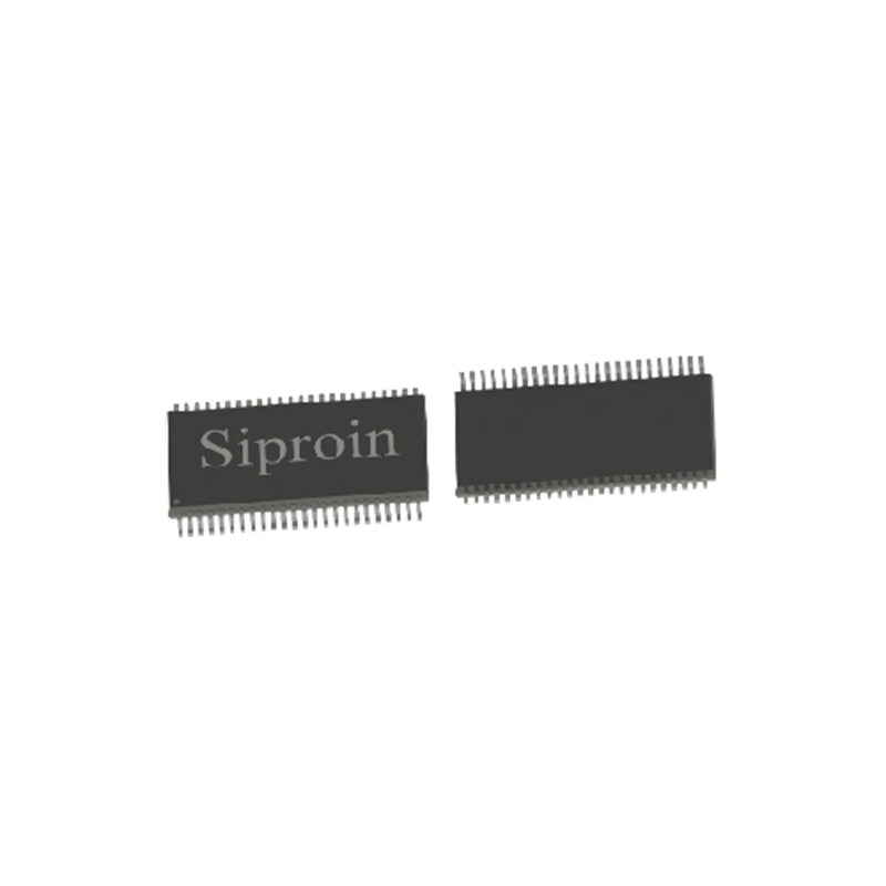
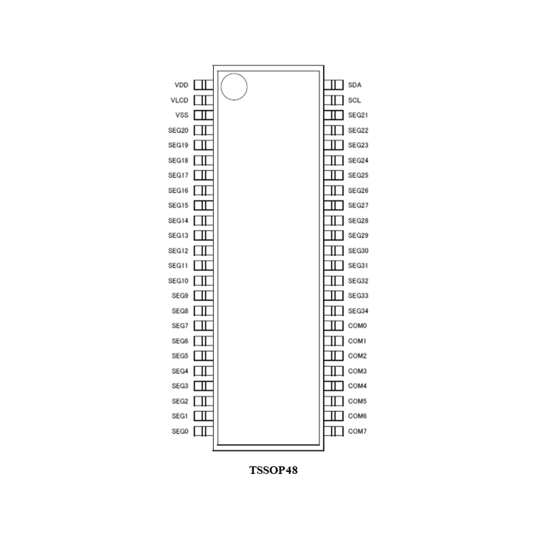
| SSP97950AFV | TSSOP48 | Reel | 2500 |
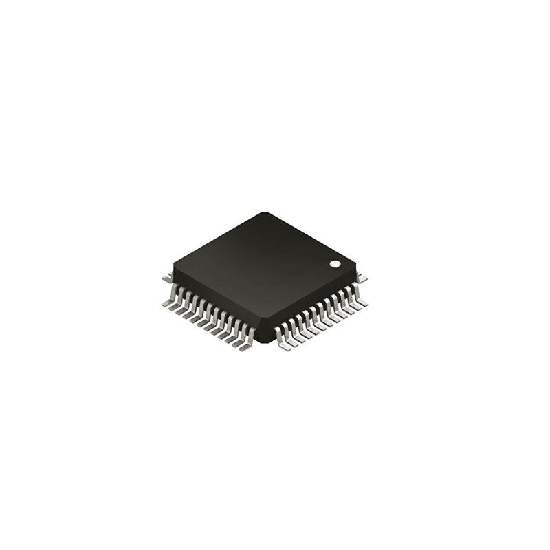
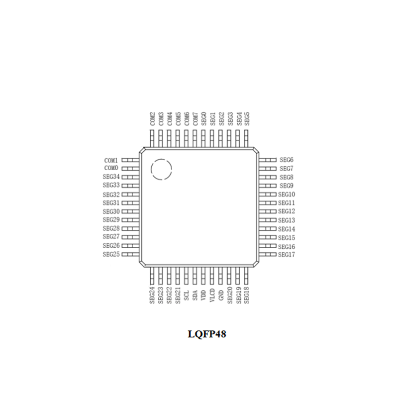
| SSP97950AKV | LQFP48 | Tray | 250 |
_画板-1@2x.png)
Shanghai Siproin
Microelectronics Co.,Ltd.
Welcome your contact.

