


Features
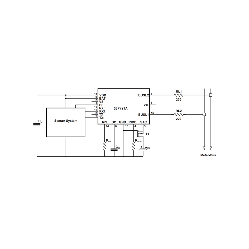
-Supply From Meter-Bus via Output VDD; -Supply From Meter-Bus via Output VDD or From Backup Battery; -Supply From Battery, Meter-Bus Active for Data Transmission Only;
| Applications
|
Blog
Features
-Supply From Meter-Bus via Output VDD; -Supply From Meter-Bus via Output VDD or From Backup Battery; -Supply From Battery, Meter-Bus Active for Data Transmission Only;
| Applications
|
Absolute Maximum Ratings
Unless specified otherwise, TA=25℃
| Parameter | Symbol | Value | Unit | |
| Bus voltage(BUSL2-BUSL1) | VMB | ±50 | V | |
| Input voltage range | Data input | RX | -0.3~5.5 | V |
| Data input inverted | RXI | -0.3~5.5 | V | |
| Logic level adjust | BAT | -0.3~5.5 | V | |
| Operating junction temperature range | TJ | -25~150 | ℃ | |
| Operating free-air temperature range | TA | -25~85 | ℃ | |
| Storage temperature range | TSTG | -65~150 | ℃ | |
| Power derating factor, junction to ambient | 8 | mW/℃ | ||
Electrical Characteristics
| Symbol | Parameter | Test Conditions | Min | Typ | Max | Unit | |||
| △VBR | Voltage drop at rectifier BR | IBUS=3mA | 1.5 | V | |||||
| △VCS1 | Voltage drop at current source CS1 | RRIDD=13kΩ | 1.8 | V | |||||
| IBUS | BUS current | VSTC=6.5V, IMC=0mA | RRIDD=13kΩ | 3 | mA | ||||
| RRIDD=30kΩ | 1.5 | mA | |||||||
| △IBUS | BUS current accuracy | △VBUS=10V, IMC=0mA,RRIDD=13~30kΩ | 2 | % | |||||
| ICC | Supply current | VSTC=6.5V, IMC=0mA,BAT=3.8V, RRIDD=13kΩ(2) | 650 | μA | |||||
| ICI1 | CI1current | VSTC=6.5V, IMC=0mA,BAT=3.8V, RRIDD=13kΩ,BUS=6.5V, RX/RXI=off(2) | 350 | μA | |||||
| IBAT | BAT current | VBAT=3.8V | -0.5 | 0.5 | μA | ||||
| IBAT=IVDD | BAT plus VDD current | VBUS=0V, VSTC=0V | -0.5 | 0.5 | μA | ||||
| VVDD | VDD voltage | -IVDD=1mA, VSTC=6.5V | 3.1 | 3.4 | V | ||||
| RVDD | VDD resistance | -IVDD=2~8mA, VSTC=4.5V | 5 | Ω | |||||
| VCTC | STC voltage | VDD=on, VS=on | 5.6 | 6.4 | V | ||||
| VDD=off, VS=off | 3.8 | 4.3 | |||||||
| IVDD﹤ISTC_USE | 6.5 | 7.5 | |||||||
| ISTC_USE | STC current | VSTC=5V | RRIDD=13kΩ | 1.85 | 2.4 | mA | |||
| RRIDD=30kΩ | 0.65 | 1.1 | |||||||
| VRIDD | RIDD voltage | RRIDD=30kΩ | 1.23 | 1.33 | V | ||||
| VVS | VS voltage | VDD=on, IVS=-5μA | VBAC -0.4 | VBAC | V | ||||
| RVS | VS resistance | VDD=off | 0.3 | 1 | MΩ | ||||
| VPF | PF voltage | VSTC=6.5V | VVB=VSTC+0.8V, IPF=-100μA | VBAT -0.6 | VBAT | V | |||
| VVB=VSTC+0.3V, IPF=1μA | 0 | 0.6 | |||||||
| VVB=VSC+0.3V, IPF=5μA | 0 | 0.9 | |||||||
| ton | Turn-on time | CSTC=50μF, Bus voltage slew rate: 1V/μs | 3 | s | |||||
Note 1:All voltage values are measured with respect to the GND terminal, unless otherwise noted.
Note 2:Inputs RX/RXI and outputs TX/TXI are open, ICC=ICI1+ICI2.
Receiver Section Electrical Characteristics(1)
| Symbol | Parameter | Test Conditions | Min | Typ | Max | Unit |
| VT | See Figure 1 | MARK-8.2 | MARK-5.7 | V | ||
| VSC | SC voltage | VVB | V | |||
| ISC_charge | SC charge current | VSC=24V,VVB=36V | -15 | -40 | μA | |
| ISC_discharge | SC discharge current | VSC=VVB=24V | 0.3 | -0.033×ISC_charge | μA | |
| VOH | TX/TXI High-level output voltage | ITX/ITXI=-100μA | VBAT-0.6 | VBAT | V | |
| VOL | TX/TXI Low-level output voltage | ITX/ITXI=100μA | 0 | 0.5 | V | |
| ITX=1.1mA | 0 | 1.5 | ||||
| ITX/ITXI | TX/TXI current | VTX=7.5V,VVB=12V,VSTC=6V,VBAT=3.8V | 10 | μA |
Note: All voltage values are measured with respect to the GND terminal, unless otherwise noted.
Transmitter Section Electrical Characteristics(1)
| Symbol | Parameter | Test Conditions | Min | Typ | Max | Unit |
| IMC | MC current | RRIS=100Ω | 11.5 | 19.5 | mA | |
| VRIS | RIS voltage | RRIS=100Ω | 1.4 | 1.7 | V | |
| RRIS=1kΩ | 1.5 | 1.8 | ||||
| VIH | RX/RXI High-level input voltage | See Figure 2(2) | VBAT-0.8 | 5.5 | V | |
| VIL | RX/RXI Low-level input voltage | See Figure 2 | 0 | 0.8 | V | |
| IRX | RX current | VRX=VBAT=3V, VVB=VSTC=0V | -0.5 | 0.5 | μA | |
| VRX=0,VBAT=3V, VSTC=6.5V | -10 | -40 | ||||
| IRXI | RXI current | VRXI=VBAT=3V,VVB=VSTC=0V | 10 | 40 | μA | |
| VRXI=VBAT=3V,VSTC=6.5V | 10 | 40 |
Note 1:All voltage values are measured with respect to the GND terminal, unless otherwise noted.
Note 2:VIH(max) = 5.5 V is valid only when VSTC > 6.5 V.

_画板-1@2x.png)
Shanghai Siproin
Microelectronics Co.,Ltd.
Welcome your contact.

